|
Handling BIM Models
|   |
|
Handling BIM Models
| |
The BIM models helps to create digital twins in construction designs where the construction schedules can be linked to the 3D design. This helps in visualizing the planned shape of construction at any given time and compare it with the actual. This enables project managers to detect project delays early and plan any rectifications in affected areas as required.
NOTE: For enabling 4D features Forge viewer is to be selected as the default viewer for BIM files.
BIM files are uploaded as Documents to SmartProject. If the document is linked with any Project, the BIM file is automatically linked with the selected Project.
In most large construction projects, it is required to monitor the progress of structural works along with the MEP works. Hence it is required to work on the main structural model and sub-models simultaneously in 4D. For using this facility, the user must attach the Revit files of the sub-models as Related files or Reference. Comments can be added and viewed. Also models can added and models that are not more required can be removed.
Viewing comments and inserting comments
Comments entered by different reviewers on the drawing can be viewed and new comments can be added.
To view comments
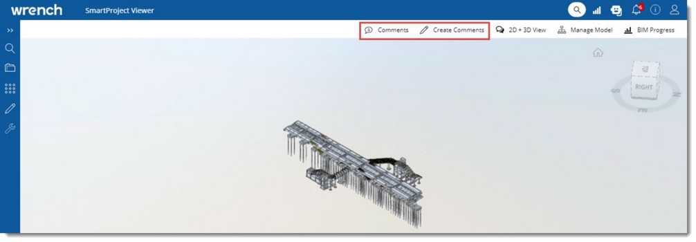
Figure: Opening BIM Model
Comments entered by different reviewers are displayed in the comment box.
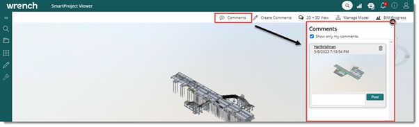
Figure: Viewing comments
To mark comments
Commenting mode is enabled and different commenting tools are displayed.
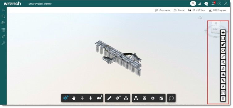
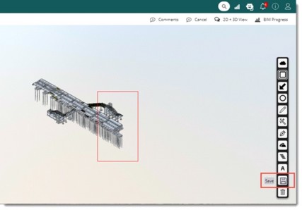
Figure: Marking comments and saving comments
The comment is saved and is displayed in the viewer.
Loading models and adding new models
In certain projects, it is required to compare one design with other main designs for interference checks. For Example: Checking interference between Civil design and the HVAC design where the two could be independent designs using separate workflows.
Hence a facility to search designs using a document search window and load the same in Viewer is provided.
To load models
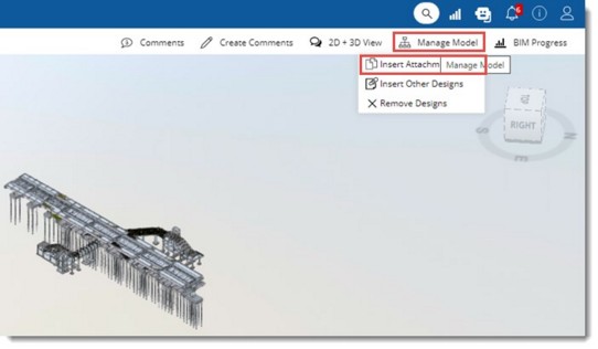
Figure: Loading models
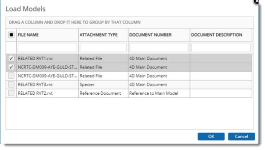
Figure: Load Models window
Here a list of all Revit files added as the Related/Reference files of the main document are displayed.
Merged models or sub-models can be viewed separately.
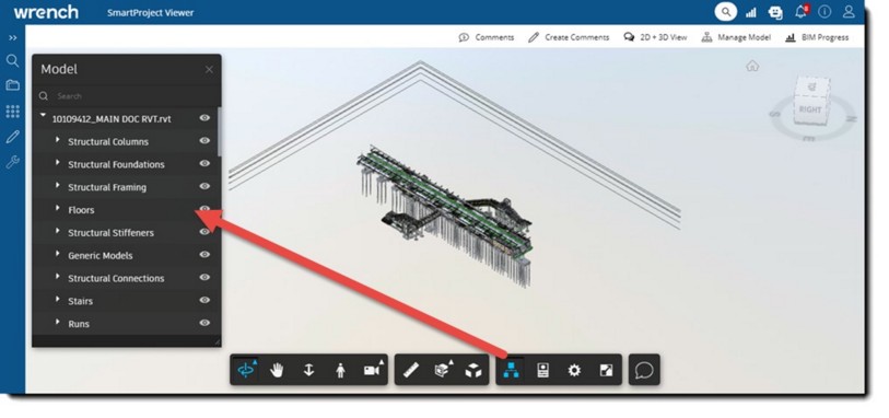
Figure: Model window
To insert other designs
Document Search window is displayed.
The selected design is displayed in the window.
Removing models linked to drawings
Models linked to drawings can be removed.
To remove a model linked to drawing
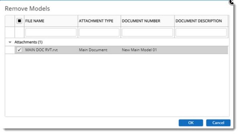
Figure: Remove Models window
To view BIM progress
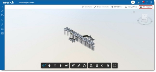
Figure: BIM Model
On clicking BIM Progress, the BIM Progress window is displayed. In the tool bar, options WBS, Legends, Create RFI and Manage Model are available.
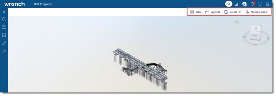
Figure: BIM Progress window
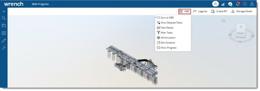
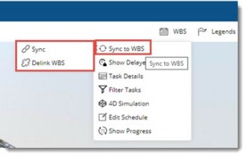
Figure: WBS Menu
Different options in the menu are explained in the following sections.
The BIM element details of the model can be synchronized to the linked WBS.
To synchronise BIM element details to WBS
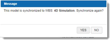
If the model is already linked (previously synchronized) to a WBS, the following warning message is displayed.
If the model is not linked to a WBS, Select WBS window is displayed.
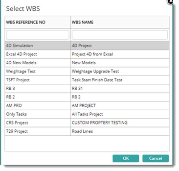
Figure: Select WBS wndow
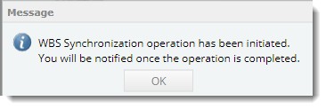
System will start to synchronize the BIM model under the selected level. The following message is displayed.

Once synchronisation is completed a notification is sent to the user. A sample notification is shown in the following figure.
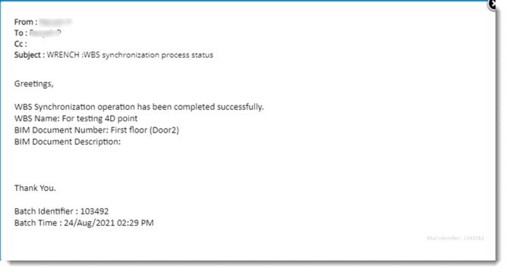
Figure: Notification window
Tasks delayed as on Current date can be viewed.
To view delayed tasks
Once validated successfully, all tasks in delayed status with a plan on or before the current date are displayed as highlighted in the viewer in red colour.
Status of tasks planned during a range of dates can be viewed.
To filter tasks
A filter is displayed.
Tasks filtered based on the date entered is displayed.
Task details against the linked task can be viewed.
To view task details
Task Details window is displayed. Details of the task is displayed.
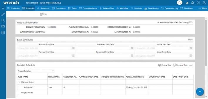
Figure: Task Details window
4D simulation of the model can be viewed.
To view 4 D simulation
4D Simulation settings window is displayed.
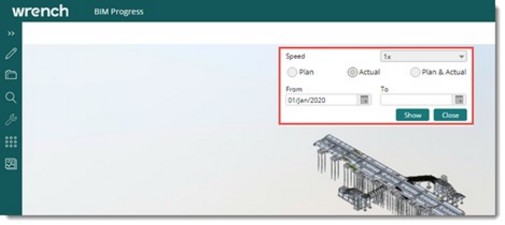
Figure: 4 D simulation settings window
Enter values for the following fields.
If the simulation is based on the planned dates and if the setting ‘Edit Schedule Dates’ is enabled for a WBS level and the dates are specified, all the tasks (elements) under the WBS level will be highlighted with the legends during a simulation on the specified date.
If the dates are not specified, all the tasks (elements) under the WBS level will not be highlighted during the simulation.
If the setting ‘Edit Schedule Dates’ is disabled for a WBS level, tasks (elements) under the WBS level will be highlighted based on the task schedules.
If the simulation is based on Actual dates and if the setting ‘Edit Actual Dates’ is enabled for a WBS level and the dates are specified, then all the tasks under the level will be highlighted in the simulation based on the specified date.
If the setting ‘Edit Actual Dates’ is disabled for a WBS level, then each task will be highlighted based on the actuals of individual tasks.
As the simulation starts, an Information window is displayed.
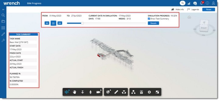
Figure: 4 D Simulation
From date and To date as specified in the setting is displayed here. Date for which the progress is being displayed in the 4D Simulation is displayed in the field Current date in simulation. This will gradually change from start to finish. The elements in the window are described in the following table.
|
# |
Property |
Description |
|
1 |
Previous |
Click this button to navigate to previous dates during the simulation. The simulation drifts to the preceding date and the details are displayed based on the planned and actuals of the preceding date. |
|
2 |
Next |
Click this button to skip the succeeding date during the simulation. The simulation drifts to the succeeding date and displays the details based on the planned and actuals of the succeeding date. |
|
3 |
Pause/Play |
Click this option to pause or resume the simulation. As the simulation starts, the Pause button is displayed. Click the Pause button to halt the simulation. On tapping the Pause button, it turns to the Play button. Click the Play button to resume the simulation. |
|
4 |
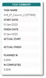
Show Task Summary |
If the checkbox next to this option is selected, during the simulation process, the details of each day's task are displayed in the TASK SUMMARY window.
The Task Summary will be hidden if the checkbox is cleared. |
|
5 |
Details |
Click the button if the user wants to change the settings when the simulation is in progress. When the user clicks the Details option, the simulation is paused and the 4D Simulation Settings window is displayed. Here the user can make necessary changes and click on the Show button to start the simulation as per recent changes. |
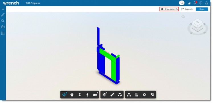
Figure: Hiding and showing information
NOTE: While simulating if a colour is configured for a rule in a task, then the colour of the element on achieving the rule is displayed configured in the rule. The colour of the task in the simulation shall be considered in addition to the existing legends in the simulation. If the simulation is based on Plan only, the elements in the simulation will not fetch the colour of the rules.
Editing Schedules
The option for editing the schedules acts as a shortcut to edit or update the planned and actual dates of an individual element or a task.
To edit schedules
The "View/Edit" Schedule window is displayed.
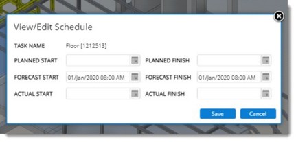
Figure: View/Edit Schedule window
The Task Name of the selected element is displayed here.
NOTE: The Sub-model Revit files can be opened in Viewer individually and can be managed using the options and facilities that are available for the main drawing.
Show Progress
Progress as of the current date without the simulation process can be viewed.
To show progress
On clicking this option, the progress of the model is displayed.
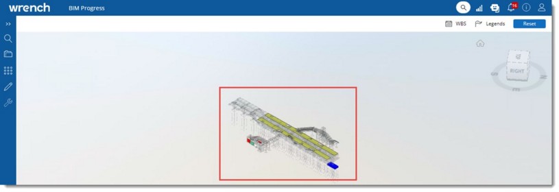
Figure: BIM Progress
The details are indicated using legends.
Planned Elements, delayed Elements and actual completed elements are highlighted using different colour legends in the 4D Model.
To view legends
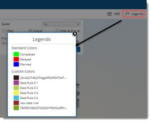
Figure: Viewing legends
Different legends to indicate Planned, Delayed and Completed tasks are displayed.
An RFI can be created based on specific BIM element. Also a general RFI can be created based on a BIM file. Create RFI’ option will be available only if the RFI module licensing is enabled in Serverconfig.
To create an RFI
RFI Details window is displayed.
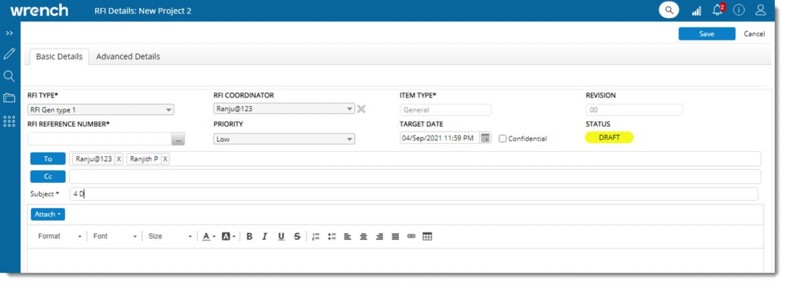
Figure: RFI Details window
If a BIM element is selected while creating an RFI, on saving the RFI, an option View BIM Element is available in the window.
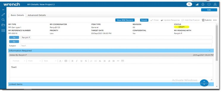
Figure: Viewing BIM Element
On clicking the option ‘View BIM Element’, the 4D simulation is opened in a new tab and the BIM element linked with the RFI will be highlighted in orange colour.
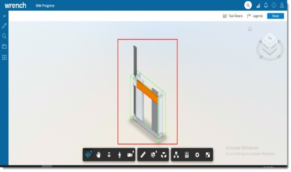
Figure: Displaying selected BIM element