|
Handling BIM Models
|   |
|
Handling BIM Models
| |
The BIM models helps to create digital twins in construction designs where the construction schedules can be linked to the 3D design. This helps in visualizing the planned shape of construction at any given time and compare it with the actual. This enables project managers to detect project delays early and plan any rectifications in affected areas as required.
NOTE: For enabling 4D features Forge viewer is to be selected as the default viewer for BIM files.
BIM files are uploaded as Documents to SmartProject. If the document is linked with any Project, the BIM file is automatically linked with the selected Project.
To view BIM progress
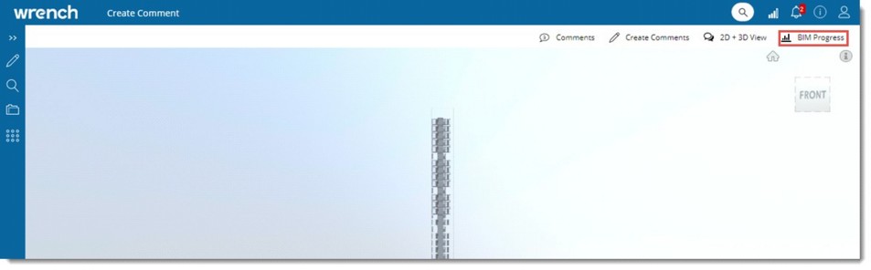
Figure: BIM Model
On clicking BIM Progress, the BIM Progress window is displayed.
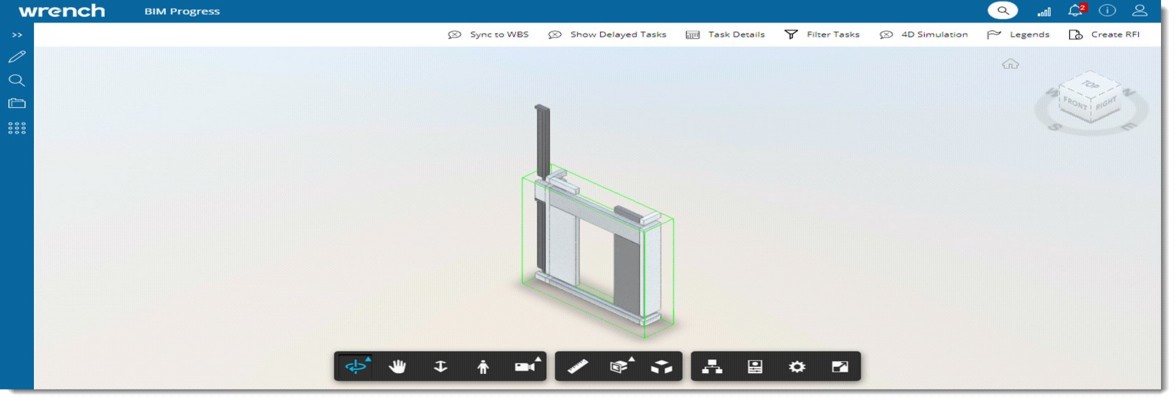
Figure: BIM Progress window
The following operations can be carried out from the tool bar.
The BIM element details of the model can be synchronized to the linked WBS.
To synchronise BIM element details to WBS
A message Are you sure to synchronize the WBS with the BIM model? is displayed.
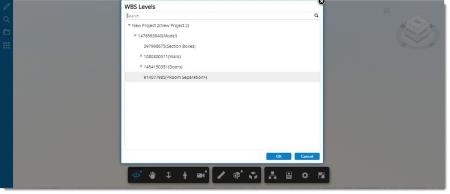
Figure: WBS Levels window
System will start to synchronize the BIM model under the selected level. The following message is displayed.
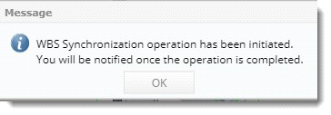
Once synchronisation is completed a notification is sent to the user. A sample notification is shown in the following figure.
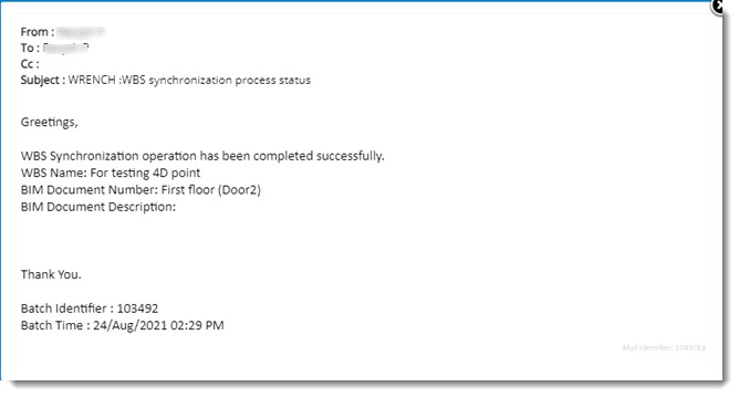
Figure: Notification window
Planned Elements, delayed Elements and actual completed elements are highlighted using different colour legends in the 4D Model.
To view legends
Different legends to indicate Planned, Delayed and Completed tasks are displayed.
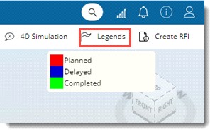
Figure: Viewing legends
Tasks delayed as on Current date can be viewed.
To view delayed tasks
Once validated successfully, all tasks in delayed status with a plan on or before the current date are displayed as highlighted in the viewer using the ‘Delayed’ legend.
Status of tasks planned during a range of dates can be viewed.
To filter tasks
A filter is displayed.
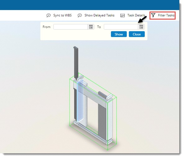
Figure: Filtering tasks
Tasks filtered based on the date entered is displayed.
Task details against the linked task can be viewed.
To view task details
Task Details window is displayed. Details of the task is displayed.
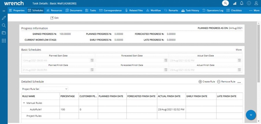
Figure: Task Details window
4D simulation of the model can be viewed.
To view 4 D simulation
4D Simulation settings window is displayed.
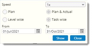
Figure: 4 D simulation settings window
Enter values for the following fields.
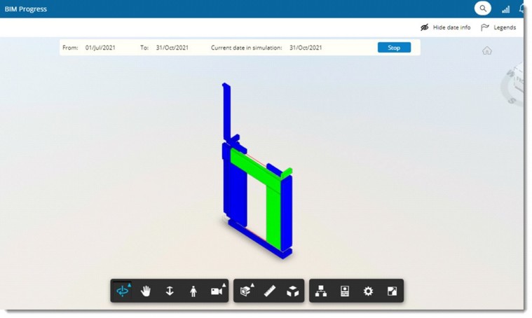
Figure: 4 D Simulation
From date and To date as specified in the setting is displayed here. Date for which the progress is being displayed in the 4D Simulation is displayed in the field Current date in simulation. This will gradually change from start to finish.
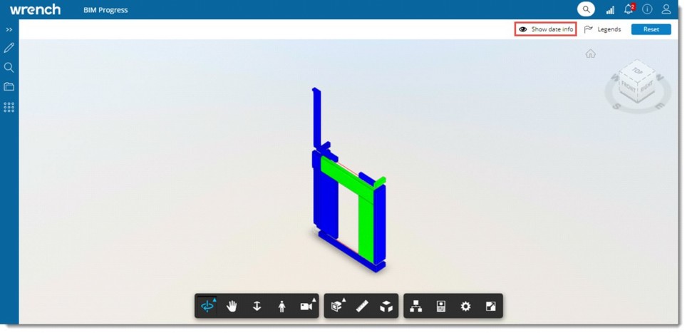
Figure: Hiding and showing information
An RFI can be created based on specific BIM element. Also a general RFI can be created based on a BIM file. Create RFI’ option will be available only if the RFI module licensing is enabled in Serverconfig.
To create an RFI
RFI Details window is displayed.
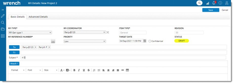
Figure: RFI Details window
If a BIM element is selected while creating an RFI, on saving the RFI, an option View BIM Element is available in the window.
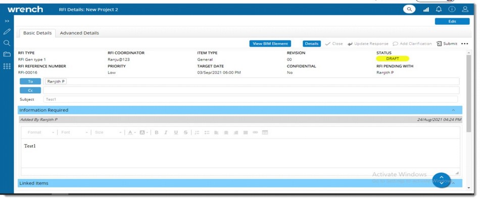
Figure: Viewing BIM Element
On clicking the option ‘View BIM Element’, the 4D simulation is opened in a new tab and the BIM element linked with the RFI will be highlighted in orange colour.
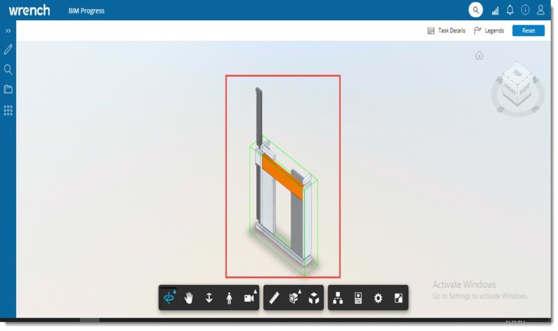
Figure: Displaying selected BIM element